Effects of Laser Mirror Surface Flatness
Authors: Jay Small
Application Note Summary
Whether or not you need to do a full analysis of your laser system to see the impacts of mirror flatness on system performance is application-dependent, but the λ/10 flatness value widely used in industry has its basis in actual analysis and is a great place to start. For a given wavelength, flatness specifications of λ/10 or better, regardless of mirror size, have practically indistinguishable effects. However, if your application requires flatness values of λ/20, additional analysis beyond just the mirrors in your system is likely warranted. Also, if the minor cost benefit of loosening flatness specifications to λ/4 could be worth it for your application, it is probably best to test λ/4 optics before making the decision to move to this looser flatness specification in volume production.
Introduction
Laser systems often require extremely precise optical components, such as mirrors and lenses, with specifications that approach the limits of what is possible to manufacture. When creating an optical system for laser use, it is important to manage one’s expectations about what is manufacturable at the desired price point. Understanding which performance factors are crucial versus which factors are desired but unnecessary can save time and money. Depending on the application, a laser system may or may not require high-performance custom optical components. This application note will demonstrate this point by exploring the simulated effects of mirror surface flatness on the focused spot size of an input Gaussian laser beam propagating through a simulated laser materials processing system.
This application note has implications for any laser system, including one or more laser mirrors. To maximize laser system efficiency, laser mirrors are usually coated with ion-beam-sputtered (IBS) coatings or evaporative coatings. IBS coatings are popular mirror coating types for their extremely high spectral performance, meaning that they can achieve very high reflectivities. However, they do put very high stress on the surface to which they are applied, potentially warping the surface of the mirror unless a compensating coating on the backside of the optic or a lengthy annealing is applied. Evaporative coatings only apply a small amount of stress to the mirror surface, but their spectral performance is lower than that of IBS coatings. While this application note does not directly explore the effects of coatings, the simulated mirror curvatures approximate curvatures imparted to mirrors from the residual stress imbalance of an IBS-coated mirror.
Optical Limits and Guidelines
Surface Flatness
The high-quality optical mirrors Edmund Optics® offers for laser applications specify surface flatness over a clear aperture ($CA$). A peak-to-valley (PTV) surface flatness refers to the maximum deviation of the surface from its nominal planar form. If expressed in waves, this measurement is commonly done in a double-pass reflection instrument such as a Fizeau Interferometer at a test wavelength $λ$. Thus, a largest physical deviation $h$ would have PTV surface flatness $SF$:
Furthermore, while a specified flatness is expressed in fractions of a wavelength, this applies to an indicated $CA$, typically 85-90% of the physical diameter. As we will illustrate, the $SF$ and the $CA$ must be taken together to understand the impact on a beam delivery system.
While, generally, a given surface flatness error can arise from many possible patterns of physical deformation, the symmetry and dominance of net stresses imparted by coatings on a circular mirror substrate naturally give rise to a spherical surface geometry. These can be accurately described as a very shallow spherical surface with a large curvature radius. Curvature is defined as the reciprocal of the radius of curvature (Equation 2).
In order to represent mirror flatness as a curvature, we can take the maximum sagitta ($sag$) of the spherical surface as the value $h$ in Equation 1.
To expand the equation for sag we must consider the clear aperture represented as semi-diameter $ρ$ (Equation 4).
With the surface flatness and the clear semi-diameter, the radius of curvature can be determined (Equation 5).
Since the sag of the mirror is many magnitudes smaller than the radius of the mirror, the contribution of the first term to the radius of curvature is insignificant $\left( \frac {ρ^2}{h}≫h \right)$. It is, therefore, reasonable to use the parabolic approximation to simplify Equation 5 to Equation 6.
Now, we express the radius of curvature in terms of the flatness specification in waves by substituting Equation 1 into Equation 6 (Equation 7).
We see now how the clear aperture specification and flatness specification together determine what curvature radius represents the error. Considering that a smaller curvature radius represents a larger flatness error, we see from Equation 7 that a larger optic will have significantly smaller error for a given $SF$ value.
This is important to understand when determining what flatness specification is required in your system. For example, EO mirror #38-841 has a mechanical diameter of 50.8mm and semi-diameter of 25.4mm. With a clear aperture of 90%, the clear semi-diameter (𝜌) of the mirror is 22.86mm. With a surface flatness of $λ⁄10$ and using a testing wavelength of 632.8nm, the radius of curvature calculated with Equation 7 is approximately $8.3×10^6 mm$ and the curvature is $1.2×10^{-7}mm^{-1}$.
On the other hand, a similar but smaller mirror #38-838 has mechanical diameter 38.1mm and $CA$ semi-diameter (𝜌) of 19.4mm. The surface flatness is the same $λ⁄10$, but Equation 7 gives radius $4.7×10^6 mm$ and curvature $2.2×10^{-7}mm ^{-1}$. Because the flatness specification is the same for both mirrors, the possible absolute error of the smaller mirror is larger by the ratio of their clear apertures:
However, is the lower absolute flatness error really required for your system? In this application note, we will examine some example scenarios to better understand how to answer this question.
The Diffraction Limit
The lower limit spot diameter that a Gaussian laser beam having ideal beam quality $M² = 1$ can be if focused by an aberration-free lens of positive focal length $f$ is dependent on the input beam waist radius $ω_0$ and the laser wavelength $λ$ (Equation 9).
Spot diameter $D$ here is measured as the width where the spot intensity is $1⁄e^2$ of its peak value. $D$ is also dependent on the input waist position and size before the lens. However, we simplify this dependency here by assuming the input waist position is one focal length distant from the lens and that the input beam diameter $(2ω_0)$ at the lens is at most $≈1/2$ the lens diameter. A more detailed treatment on this effect is found here, but these constraints represent a common boundary condition of typical systems where Equation 9 is valid.
For example, a 1064nm laser beam with a diameter of $2ω_0=5mm$ and $M^2=1$, focused with a 100mm lens, has a diffraction-limited spot $Ø$ of $D=27µm$.
Ansys Zemax OpticStudio Simulation & Results
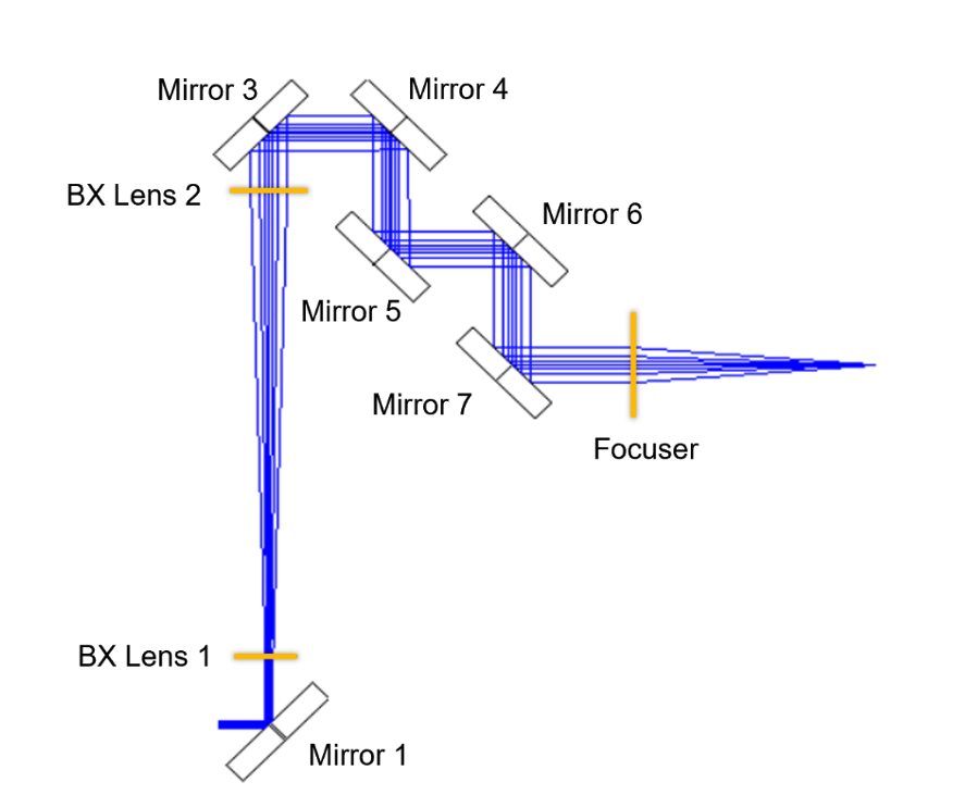
To illustrate the effects of mirror curvature on a laser beam, a delivery layout having commonly employed architecture elements was created with Ansys Zemax OpticStudio 2024 R1.03. The model uses a paraxial beam expander, seven identical mirrors, and a paraxial focuser arranged so that the beam lies in one plane. Paraxial transmissive elements are used to analyze only the aberration contributed by the mirror flatness errors (Figure 1).
The following analysis is particular only to the number and reflection angle of mirror elements, and that one beam axis lies in a single plane. Otherwise, the fold mirrors could be placed in any arrangement and spacing so long as the reflection angle is 90°, as shown.

Astigmatism
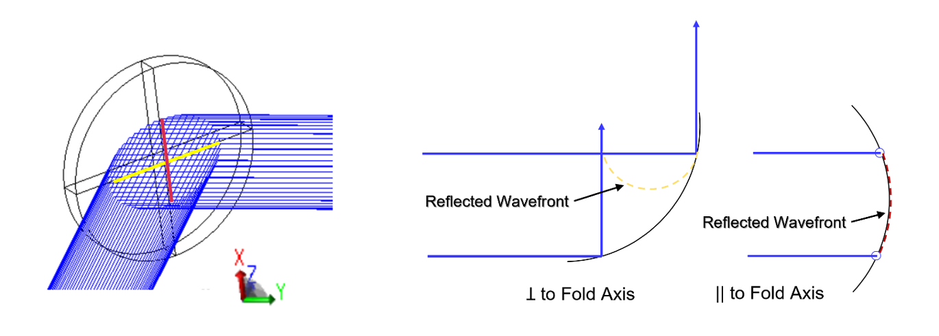
In a folded mirror system with flatness error modeled as above, the aberrations present are nearly purely astigmatism. This mechanism is qualitatively illustrated in Figure 2.

The beam width and the radius of curvature from the flatness error are constant. However, we see that the reflected wavefront ꓕ to the fold axis is projected across the curvature at the reflection angle, subjecting it to more of the optically powered surface than that || to the fold axis. Thus, the wavefront emerges with a more severe curvature. The imbalance is astigmatism, which accumulates additively at every turn mirror in this way. Furthermore, the ꓕ direction will accumulate optical power regardless of the reflection direction, so long as the beam lies in a single plane.
Effect on Laser Beams
The amount of tolerable astigmatism in a laser beam is entirely application-specific. Often, astigmatism is unavoidable, and the compromise is to use the best and smallest circular spot found midway between the two astigmatic foci. We can analyze this spot location throughout degrees of flatness and investigate the effects of wavelength, beam diameter, and mirror size. For example, a larger beam requires larger mirrors than smaller beams. The mirrors are specified with the same measured flatness of $λ/10$ PTV, but the absolute error, referring to Equation 7, is different because of the designated clear aperture size.
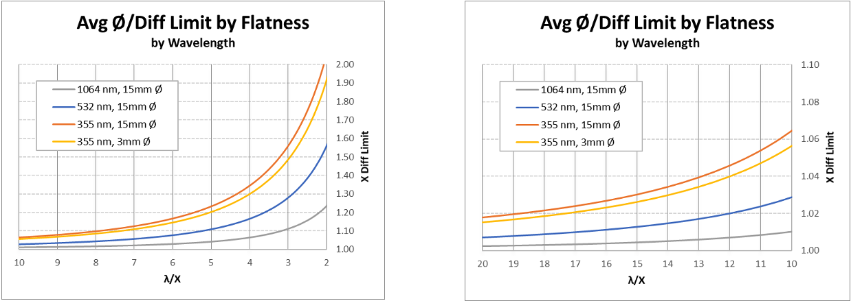
If we plot the ratio of the resulting spot size to the diffraction-limited spot size, we can scale the system for a variety of input beam sizes and focuser focal lengths. One example uses a 3mm input beam and a 1X and 5X beam expander to achieve a 3mm and 15mm input beam, respectively, incident to Mirror 2. The focuser focal length is arbitrary (Figure 3).
 Figure 3: Resulting average spot Ø ÷ diffraction limited Ø vs flatness specification after seven mirror reflections by input beam diameter (left) and by focused spot size (right). The larger beam requires larger mirrors; therefore the absolute mirror flatness is different for each system. In both cases, the error ratio is near unity by λ/5 and virtually diffraction limited out to λ/10. Gains beyond λ/10 are quite small in this example system.
For the 15mm beam system, the mirrors are 50.8mm Ø as required to contain the beam. The 3mm beam system can use 12.7mm Ø mirrors, both sizes having 90% $CA$. These plots illustrate a tradeoff at play. The smaller mirrors have 16X higher absolute power error due to a smaller radius of curvature per Equation 7, but interact with less beam area due to the relatively smaller beam. Thus, for a given wavelength, flatness specifications of $λ/10$ or better, regardless of mirror size, have practically indistinguishable effects if appropriately sized for the intended beam.
Shorter wavelengths are, however, more sensitive to mirror flatness overall. Recall that $λ$ in the above relations is the test wavelength, typically the HeNe laser line 632.8nm. So, when used with a laser at ½ the test wavelength, the effect of flatness error on the wavefronts will be twice as great. Figure 4 illustrates these characteristics where we see a spot Ø error of 1.02 X the diffraction limit could be achieved with $λ/5$ for 1064nm, but would require $λ/20$ for 355nm.

Summary and Recommendation
In this idealized treatment of mirror flatness, we model the error as exclusively due to coating stress distribution and purposefully ignore aberration effects of all other beam transfer optics to gain a sense of the scale that mirror flatness error degrades a laser system. In actuality, other surface errors exist on mirror surfaces. These become increasingly relevant as the flatness error caused by coating stress is better controlled. Therefore, additional analysis is likely warranted if an application is sensitive enough to demand $λ/20$ mirror flatness.
We have shown that selecting a larger or smaller mirror will not play a significant role in how coating-induced flatness error affects the laser beam. Beam size, though, can be an important factor for high peak or average power lasers with respect to the laser damage threshold (LDT) of the mirror coatings. A larger beam, and therefore larger mirrors, may be required to keep the beam intensity within the range specified on the mirror. However, as we have shown, this will not come at a sacrifice to mirror flatness effects.
More Resources
- High Reflectivity Mirrors for Laser Applications Webinar Recording
- Understanding and Specifying LIDT of Laser Components Application Note
- A Guide to (Not Over) Specifying Losses in Laser Optics Application Note
- Metrology for Laser Optics Application Note
- Key Parameters of a Laser System Application Note
- Laser Optics Lab Video Series


or view regional numbers
QUOTE TOOL
enter stock numbers to begin
Copyright 2023, Edmund Optics Inc., 101 East Gloucester Pike, Barrington, NJ 08007-1380 USA
California Consumer Privacy Acts (CCPA): Do Not Sell or Share My Personal Information
California Transparency in Supply Chains Act